|
|
|
|
|


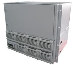
GPE48350E,Rectifier,DC48V,350A,Modular Rectifier System,With Monitoring Module,Software
Product Details:
Payment & Shipping Terms:
|
Detailed Product Description
Power System of High Performance and High Reliability
GPE48350E Embedded Power System
Input:90~290Vac; Output: -42~-58Vdc;
The GPE48350E embedded power system consists of the power distribution frame, monitoring module and rectifier module, with functions of AC lightning proof and DC power distribution. The monitoring module supports outside signal input, communication transformation, AC/DC detection and contactor control. The whole system is of high reliability and performance, and can be operated through PC software.
Application
■ Small scale program controlled exchanger
■ Access network
■ Transmission equipment
■ Mobile communication
■ Satellite communication ground station
■ Microwave communication
Main features
Adoption of active power factor compensation technology with factor >0.98
Wide operating range of AC input voltage: 90~290Vac
Operating temperature range: -25°C~+55°C
Zero current/voltage switching tech with high efficiency ≥91%
Lifecycle of battery prolonged by perfect battery management, including electrical charge/discharge management, battery temperature compensation, battery capacity test, reversal connection proof protection, low voltage protection etc.
Hot-swappable
Input over/under voltage protection
Output over voltage protection
Output over current protection
Output short circuit protection
Auto current sharing, parallel output
Embedded mounting
1. General Introduction
1.1 System Configuration
The system consists of power distribution unit, rectifier module (from 1 set, up to 7 sets) and 1 monitoring module. The configuration is optional, as following table:
|
Configuration |
Rectifier Module |
Monitoring Module |
Power Distribution |
Remark |
|
Standard |
GPR4850D |
GPM48P (With Ethernet Port) |
AC power distribution: 3-phase, 5-wire input, 3-pole AC breaker @ general line (63A/3P) and guide rail type terminal; DC power distribution: battery MCB 125A/2P; LVLD: 63A×4 32A×3 16A×4 (MCB capacity optional) LVBD: 16A×6 (MCB capacity optional) |
For details, please refer to the specifications of modules. |
1.2 Operating Principle
AC power is first input AC-INPUT MCB and then feed into the rectifier module after lightning proof and filtering. AC-INPUT acts as protection to over load and short circuit to AC power. The user’s battery is connected to the DC output side through MCB BAT and KM2, and the circuit breaker provides disconnection control, over-load and short-circuit protection to the battery.
Under normal conditions, every parameter of rectifier modules and power distribution unit are all under control of the monitoring module, operating according to the pre-set parameter or user’s commands. If AC mains faults, the battery will power to the system. With the battery discharge, the terminal voltage of the battery starts to descend. When battery voltage is under -47V±0.5V, the monitoring module sends DC under voltage alarm signal and when battery voltage is under -46.0V±0.5V (adjustable), the KM1cuts off non-priority loads and retaining power to priority loads. If battery voltage drops to -43.0V±0.5V (adjustable), the KM2 will cut off output of priority loads and then the power system will stop working. If the external AC mains recovers, the system will normally work again. (All above monitoring data are system default values and can be reset by user).
Except for battery over-discharge protection, battery or load over-temperature protection is prohibitive under default, users can send command to activate or inactivate according to the demanding.
2. System Properties
|
Environment |
|||||
|
Item |
Min. |
Typical |
Max. |
Unit |
Remark |
|
Operating temperature |
-25 |
|
55 |
°C |
When ≥55°C, decreased power output |
|
Storage temperature |
-40 |
|
80 |
°C |
|
|
Humidity |
10 |
|
90 |
% |
Relative humidity without condensing |
|
Atmospheric pressure |
70 |
|
106 |
KPa |
|
|
Altitude |
0 |
|
3000 |
m |
|
|
Cooling |
Forced cooling with fan |
||||
|
Input |
|||||
|
Item |
Min. |
Typical |
Max. |
Unit |
Remark |
|
Input voltage range |
90 |
220 |
290 |
Vac |
|
|
Input frequency |
45 |
50 |
65 |
Hz |
|
|
Max. Input current |
|
|
40 |
A |
|
|
Power factor |
0.98 |
|
|
|
Rated load |
|
Input over voltage protection point |
300 |
|
|
Vac |
Automatically recoverable |
|
Input over voltage recovery point |
290 |
|
|
Vac |
Return difference ≥5V |
|
Input under voltage protection point |
|
|
85 |
Vac |
Automatically recoverable |
|
Input under voltage recovery point |
|
|
90 |
Vac |
Return difference ≥5V |
|
Input over current protection |
|
|
|
|
MCB in AC Input supply protection |
|
Output (Table 1) |
|||||
|
Item |
Min. |
Typical |
Max. |
Unit |
Remark |
|
Output voltage |
42 |
53.5 |
58 |
Vdc |
Adjustable by monitor, tested in no load |
|
Output power |
|
18725 |
|
W |
18725W output when input voltage is 176~290VAC (rated power includes battery charging power plus load power) |
|
|
9350 |
|
W |
90~175VAC input |
|
|
Output over voltage protection point |
58.5 |
|
60.5 |
Vdc |
Lock up |
|
Output current limiting protection point |
|
|
|
|
Output current limiting protection |
|
Output short circuit protection |
|
|
|
|
Long-term short circuit protection, automatically recoverable |
|
Over temperature protection |
|
|
|
|
Automatically recoverable in ambient temperature lower than 65°C |
|
Battery power-down protection |
|
|
|
|
Battery power-down protection |
|
Battery polarities reversal connection protection |
|
|
|
|
No damage on battery and power system |
|
Voltage regulation accuracy |
|
|
±1 |
% |
|
|
Output (Table 2) |
|||||
|
Item |
Min. |
Typical |
Max. |
Unit |
Remark |
|
Temperature coefficient |
|
|
±0.2 |
‰/℃ |
|
|
Current sharing unbalance |
|
|
±5 |
% |
Within 50~100% load range |
|
Start-up/shut-down overshoot range |
|
|
±5 |
% |
Any module is removed when operating, (the load current should be less than total output current of working rectifier modules), the system output voltage fluctuates |
|
Dynamic response recovery time |
|
|
200 |
uS |
25%~50%~25% load variation 50%~75%~50% load variation |
|
Dynamic response overshoot |
|
|
±5 |
% |
Rated output voltage, rated load current |
|
Efficiency |
91 |
92 |
|
% |
220Vac input, rated output voltage, rated load current |
|
83 |
|
|
% |
110Vac input, rated output voltage, rated load current |
|
|
Start-up time |
3 |
|
8 |
S |
pre-current limiting is fitted with start-up output between rated start up input voltage and rated output voltage established period |
|
Pressure drop |
|
|
500 |
mV |
|
|
Peak-peak noise voltage |
|
|
200 |
mV |
|
|
Psophometrically weighted noise voltage |
|
|
2 |
mV |
|
|
Other Parameters |
|
|
Item |
Requirement |
|
Acoustic noise |
≤55dB(A) |
|
Smelling |
any abnormal and poisonous smelling is not allowed |
|
Components |
rated temperature of the electrolytic capacitor ≥105℃ |
|
Hot swappable |
the rectifier module meets the hot-swappable requirement |
|
Mixed insertion |
rectifier modules can be mixed insertion |
|
Ineffective separation |
rectifier module can separate with system when it is ineffective |
|
Cooling |
forced cooling by fan mounted on rectifier, face in, back out. The fan is mounted on rectifier front panel; can be disassembled. Fans include temperature control speed adjusting function. |
|
Insulation Rating |
|||||
|
Parameters |
Min. |
Typical |
Max. |
Unit |
Remark |
|
Input-chassis |
|
3535 |
|
Vdc |
|
|
Input-output |
|
3535 |
|
Vdc |
|
|
Output-chassis |
|
1414 |
|
Vdc |
|
|
Insulating Resistance |
In normal atmospheric pressure, when relative humidity is 90%, testing voltage is 500VDC, the insulating resistance of input-output, input-grounding, output-grounding are all ≥10MΩ |
||||
3. Mechanical Properties
|
Mechanical specifications |
|
|
Dimensions (Overall) |
as the following diagram |
|
Weight(kg)(Overall) |
≤41.5kg (Inclusive of module) ≤23kg (Frame + Distribution, exclusive of module) |
![]()
4. Installation Instruction
4.1 Installation Dimension
4.2 Installation
First insert the embedded power system to the specified location till the system is well fixed. Keep the 8 fixing holes on the bracket in line with those on the cabinet and then screw up 8pcs M6 cross rounded head screws. Finally complete the installation after tightening the screw.
Note: The cabinet shall be provided by the use
5. Electric Connection
5.1 Electrical Connection
Chassis connects with external electric through system interface board. As shown in figure below:
MCB descriptions:
(1)3-phase AC input MCB and rail type connector; aa
(2)AC SPD;
(3)LOAD (-): system load- (17 MCBs);
(4)BAT (-): battery- (MCB);
(5)LOAD (+): system load+ (copper bar at front of system),
BAT (+): battery+ (copper bar at front of system)
5.2 Process of Electric Connections
Electric connection between main cabinet and external equipment includes: connection of AC input line, connection of DC output and battery, connection of communication cables, connection of GND cables. The main requirements of electrical connection are safety and reliability. The following are detailed description.
(1) AC input cable connections
The connectors for AC input cable are 3PIN MCB and rail type connector at the front panel of system. The AC cable can be directly crimped to MCB input terminal.
(2) Connection of DC load cables
The load connection connectors of power system are 17 MCBs, locating on the front panel of the
system. The cable can be directly inserted to the MCB.
a. The specifications and model of the cables shall be according to the engineering design requirements.
b. Connect one end of positive connection cable to the positive copper bar at the front of system;
c. Connect one end of negative connection cable to the MCB at the front of system;
(3) Connection of DC battery cables
Connection terminal of system and battery is MCB, indicated as BAT(-). The cable can be directly inserted to the MCB and tighten the screws. The detailed process of battery connection is as following:
a. Prepare positive connection cables and negative connection cables(including terminals and polarity identifications ready).
b. Fasten up the battery connection cable
c. Connect one end of positive connection cable to the positive copper bar at the front of system;
d. Connect one end of negative connection cable to the MCB at the front of system;
(4) Recommended cable specifications
|
Item |
Sign |
AWG/ Min. section(#/mm2) |
AWG / Max. section(#/mm2) |
Temp rating(℃) |
Withstand voltage (V) |
|
Output load wire |
Load3, Load3- Load4, Load4- |
6#/10 |
4#/16 |
105 |
600 |
|
Input GND wire |
PEin |
9#/6 |
6#/10 |
105 |
600 |
|
Mains neutral wire |
Nin |
6#/10 |
4#/16 |
105 |
600 |
|
Mains live wire |
Lin |
6#/10 |
4#/16 |
105 |
600 |
|
Battery + |
(BAT +) |
2#/35 |
1#/50 |
105 |
600 |
|
Battery - |
(BAT -) |
2#/35 |
1#/50 |
105 |
600 |
(5) Connection of GND cables
PE connection: The GND section is near the left bracket of system. Connect the chassis GND point of system main cabinet and external earth with cable of 10mm2 above.
(6) Connection of communication cables
LAN and RS-485, communication interface of GPE48350E, locates at the monitoring module, function for communication with the host.
LAN Ethernet communication code: Directly connect to the PC with cross wires or with common wire through a router.
RS-485 communication mode:
a. Connect one end of communication cable to RS-485 interface on monitoring module of GPE48350E.
b. Pin2 of communication cable linked to RS-485+ at RS-485 converter (RS485 to RS232) , Pin3 linked
to RS485- at RS-485 converter, connect COM interface of PC through RS232 port on the converter.
5.3 Instruction of Interfaces on the Back Panel
The rectifier modules and monitor module are connected on back panel of system GPE48350E, through which DC output goes to current collection bar; control signals of the monitor modules drives the contactor; SPD within distribution frame transfers signals to monitor; monitoring module and rectifier module communicate with each other; signals of current sharing goes into monitoring module.
Draft of Back Panel Design
Interfaces list is as following:
|
Contactor NO. |
Terminal type |
I/O |
Signal function |
Other panel, contact and signal connected |
Remark |
|
J2 |
AC voltage (A phase) detection |
I |
AC voltage (A phase) signal input |
AC A phase voltage |
None |
|
J3 |
AC SPD alarm signal |
I |
AC PSD alarm signal input |
AC PSD connection alarm signal |
None |
|
J4 |
Battery conactor control signal |
0 |
Battery contactor control signal output |
Connection between cable and contactor coil |
Installation requirement marked on coil terminal of sample signal |
|
J5 |
Battery current sharing interface |
I |
Battery current sharing sample signal input |
Cable connection current sharing sample signal |
Cable of sample signal includes positive and negtive ones |
|
J6 |
Load contactor control signal interface |
O |
Load contactor control signal output |
Cable connection contactor control coil |
Installation requirement marked on coil terminal of sample signal |
|
J7 |
Load current sharing signal interface |
I |
Load current sharing sample signal input |
Sample signal of cable connection current sharer |
Cable of sample signal includes positive and negative ones |
|
CON8 |
Load and battery output signal detection terminal |
I |
Load and battery signal detection input |
None |
Attention: D18-D19 battery D1-D17 load |
|
CON1, CON2, CON3, CON4, CON5, CON6, CON15 |
Rectifier module interface |
I/O |
Rectifier signal input and output, rectifier power output |
None |
None |
|
CON7 |
PMU 96PIN connector |
I/O |
Monitor signal input and output |
Terminal connects with PMU |
None |
6. GPE48350E Distribution Frame
![]()
7. Instruction of GPM48P
7.1 Monitor Module Function
|
Function |
Remark |
|
Remote monitoring of the host |
The host can conduct enquiries, settings and control upon the monitoring and realize the remote message, remote sense and remote control. |
|
Rectifier management by monitoring module |
To send controlling orders to or get data from the rectifier module via RS485 communication. |
|
Battery management |
To manage the low voltage, power down, equalizing/float charge, temperature compensation and capacity testing of the battery. |
|
Output management by monitoring module |
To inspect and control the system |
|
LED indicator |
Signal indication |
|
6 dry contacts output |
Dry contact setting |
|
COM port signal |
RS485,LAN |
|
LCD display |
to conduct setting and modification on the menu |
|
For details, please refer to specifications of “GPM48P”. |
|
7.2 PC Software
Please refer to “Instruction of PC Software” documents for the detailed information.
8. GPR4850D Rectifier Module
8.1 Instruction of Rectifier Parameters
|
Item |
Unit |
Min. |
Typical |
Max. |
Testing conditions |
|
AC input voltage |
Vac |
90 |
220 |
290 |
|
|
AC input voltage frequency |
Hz |
45 |
50 |
65 |
Rated load |
|
Input power factor |
|
0.99 |
|
|
Rated voltage/rated load |
|
Output voltage range |
Vdc |
44 |
53.5 |
58 |
|
|
Output current |
A |
0 |
50 |
|
176~290V AC input |
|
A |
0 |
22 |
|
90~175V AC input |
|
|
Output voltage withstand regulation |
|
|
|
±1% |
|
|
Peak-peak value Vp-p |
mV |
|
|
200 |
Tested with each of 0.1uF ceramic capacitor and 10uF electrolytic capacitor with 20MHz band width. |
|
Output power |
W |
0 |
2900 |
|
When 176Vac~290Vac input, 2900W output is met with |
|
W |
0 |
1200 |
|
90Vac~175Vac input |
|
|
Output efficiency |
% |
92 |
93 |
|
220V AC input (1. when input voltage is 220Vac, rated output voltage, 25% above rated load current. 2. up to 94%) |
|
% |
86 |
|
|
110V AC input |
|
|
Input over voltage protection |
Vac |
300 |
|
|
Automatically recoverable |
|
Input over voltage protection recovery point |
Vac |
290 |
|
|
|
|
Input under voltage protection |
Vac |
|
|
85 |
Automatically recoverable |
|
Input under voltage protection recovery point |
Vac |
|
|
90 |
|
|
Output over voltage protection point |
V |
58.5 |
59 |
60.5 |
1. module internal failure will result in over voltage and module itself locked up 2. when external voltage above over voltage protection point is added, module works normally. |
|
Output current limiting protection |
A |
54 |
|
|
Automatically recoverable |
|
Short circuit protection |
A |
long-term short circuit is available, automatically recoverable |
|||
|
Over temperature protection |
|
Automatically recoverable under 65℃ ambient temperature |
|||
|
The detailed information is listed in GPR4850D rectifier specification |
|||||
8.2 Installation of Rectifier Module
Handles on panel of rectifier module are equipped. When inserting module into the main cabinet, the operator shall clutch the handle with one hand while holding it with the other hand. Slowly push the module into its slot until the connection terminal on back of the module inserted into corresponding socket of system bar in the main cabinet. Finally, finish the installation by firmly fixing the screw on the panel to the main cabinet. When removing module from the main cabinet, first screw off the bolt on panel then slowly remove the module from its slot while clutching the handle.
9. System Maintenance
(1) Failure: yellow LED on rectifier module flickers continuously, communication fails;
Maintenance solution: check the communication network to see whether the internet connection is loose or internet interface is damaged or not.
(2) Failure: yellow LED on rectifier lights on;
Maintenance solution: check whether the fan is blocked, load current exceeds the max. value; AC voltage is too lower, then the auto rate decrease starts; over temperature pre-alarm starts; remote shut-down is started on PC software.
(3) Failure: Red LED on rectifier lights on;
Maintenance solution: check whether the voltage is too high/too low and over/under voltage protection is on; fan is blocked; ambient temperature is too high; load is short circuit or not.
If above mentioned parts are ok but the red LED is still on, then there is problem on the module, please return it to factory for repairing.
(4) Failure: Yellow, red, green LEDs on rectifier are all off;
Maintenance solution: Firstly check whether AC input is available or not, if not, then check the electrical circuit; if yes, the module is in malfunction, please return the module to factory for repairing.
Contact Details
Other Products
-
EVCSE48400 power 23.2KW Rectifier With Wide Voltage Range Industrial Power Supply
-
GPE48200N,Telecom Power System/UPS/Rectifier/Switching Power,DC48V,200A,With Software,SNMP Protocol
-
GPE48150A,Telecom Power System/Base Station Rectifier,Input:90~290VAC,Output: -42~-58VDC
-
GPE48120N,Rectifier,DC48V120A,With Monitoring Module,RS485/232,Ethernet Communication Port
-
GPE4860C,Embedded Telecom Power System,DC48V,60A,Modular Rectifier System,Monitoring Unit
-
Telecom Power System, UPS, Rectifier, Input: 90~280Vac; Output:-43.2~-57.6Vdc; Power:6420