|
|
|
|
|

SM2400 Environment Monitoring Unit, with RS485/RS232/Ethernet Communication Interface
Product Details:
Payment & Shipping Terms:
|


Detailed Product Description
SM2400 Environment Monitoring Unit
1.1 Summary
The SM2400 Environment Monitoring Unit is a device used for monitoring working environment conditions inside telecom room or power room. It uses dual core processing. The power supply uses DC/DC module. The measuring channel, power supply, and communication interfaces are electrically isolated, so the monitoring unit has high reliability. The MCU control design has functions of self management and self correction. SM2400 monitoring unit support RS485/RS232/Ethernet communication method. With the communication interfaces, it can realize many kinds of communication modes, such as point to point communication, point to multipoint communication, wireless remote communication, which can meet the need of various system networks.
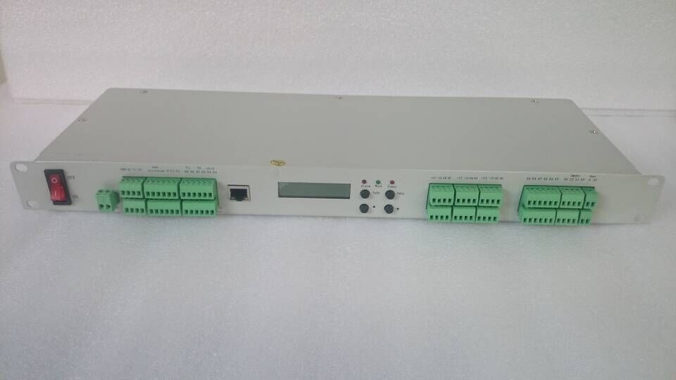
1.2 Control Board
Diagram 1.1 shows the control board of the environment monitoring unit. It includes one LCD screen, four operating buttons, three working indicator lights, multiple wiring ports and one power supply switch.
(1) Power Switch: turn on or turn off power.
(2) LCD Display Screen:
It shows different contents under the following three status.
Operating Mode: the first line shows indoor temperature and humidity; the second line shows the real-time clock, among which the first letter “A” stand for automatic output, ”M” stand for manual output. One can directly revise DOx register to amend the output status.
Menu Mode: can select eleven menu items in sequence.
Parameter Mode: shows parameter name and parameter value. For detail, please check the “3 Operation and Parameters”.
(3) Four buttons:
PgDn:
At operating status: press once and release the button, enter menu operation interface;
At menu selection interface: press once to enter the selected parameter group;
At parameter status: revise, confirm and parameter page down button; a long press on the button to exit parameters and to menu interface;
At query status: select the former day’s daily record, a long press on the button to exit query and to menu interface;
▲:increasing parameter revision. Page down button for event query.
▼:decreasing parameter revision. Page up button for event query.
PgUp:
At parameter status: page up button; the function is oppose to PgDn operation;
At menu selection interface: press once to exit parameter status and come to operating status;
At query status: select the latter day’s daily record; at current daily record, press the button to exit query.
(4) Three Status Lamps:
PWR : power indicator; when it is bright, it shows being connected with DC48V;
Work : when the system is working, it flashes at 1HZ frequency;
Alarm : system alarm occur.
1.3 Wiring Ports
The ports from left to right is shown as follows. The far left is JD1.
JD1: DC48V power supply input; 1-0V; 2--48V;
JD2: temperature and humidity sensor 2 input port;
4-5V; 3-Temp2; 2-Hum2; 1-0V;
JD3: temperature and humidity sensor 1 input port;
4-5V; 3-Temp1; 2-Hum1; 1-0V;
JD4: RS485 communication port and universal digital output DO10;
1-A+, 2-B, 3-GND; 4-normal open, 5-public, 6-normal close;
JD5: universal digital output DO9, DO8, DO7:
DO9-1, 2; DO8-3, 4; DO7-5, 6;
JD6: universal digital output DO6, DO5, DO4:
DO6-1, 2; DO5-3, 4; DO4-5, 6;
JD7: universal digital output DO3, DO2, DO1:
DO3-1, 2; DO2-3, 4; DO1-5, 6;
Note:
(1) All the digital output DO can be redefined;
(2) Factory default:
DO1-door sensor; DO2-smoke sensor;
DO3-water sensor; DO4-utility power;
DO5-temperature 1 (battery compartment) alarm;
DO6-temperature 2 (equipment compartment) alarm;
DO7-system general alarm.
(3) Only DO10 can withstand 7A current, others are 1A current.
JD8: universal analog input port AI6:
1-15V, 2--15V, 3-AI6, 4-0V;
JD9: universal analog input port AI5:
1-15V, 2--15V, 3-AI5, 4-0V;
JD10: universal analog input port AI4:
1-15V, 2--15V, 3-AI4, 4-0V;
JD11: universal analog input port AI3:
1-15V, 2--15V, 3-AI3, 4-0V;
JD12: universal analog input port AI2:
1-15V, 2--15V, 3-AI2, 4-0V;
JD13: universal analog input port AI1:
1-15V, 2--15V, 3-AI1, 4-0V;
Note:(4) AI1~AI6 can be connected with standard Hall current sensor, detecting 6 way current.
JD14: universal digital input port DI4, DI3:
DI4-1(GND), 2(DI7), 3(15V);
DI3-4(GND), 5(DI5), 6(15V);
JD15: universal digital input port DI2, DI1:
DI2-1(GND), 2(DI8), 3(15V);
DI1-4(GND), 5(DI6), 6(15V);
JD16: universal digital input port DI5(Smoke):
1-GND, 2-S1, 3-S2, 4-15V
JD17: universal digital input port DI6(Water):
1-GND, 2-C1, 3-C2, 4-15V
JD18: DI7 digital input, dry contact input, standard configuration is door sensor input;
JD19: utility power detection input, detecting AC220V, DI8;
Note:
(1) Except DI8, all other universal DI can be redefined;
(2) Factory default: DI7 - door sensor; DI5 - smoke sensor; DI6 - water sensor;
1.4 Digital Input
The digital input circuits are all passive inputs, as the diagram 1.2, so the equipment output should be active output (12V).
2. Technical Parameters
(1) Analog Input: eleven way; four ways specially for temperature and humidity measurement, the other seven ways for universal AI. AI1~AI6: 0 ~ 5V, 1 ~ 5V input; AI7: internally connected with DC48V;
(2) Digital Input: eight ways; one way specially for utility power detection (220VAC input), the other seven ways for universal DI input, function redefinable;
(3) Digital Output: ten ways; universal DO output, function redefinable;
(4) Temperature Measurement Range: -50°C ~ 85°C, accuracy 0.1 °C; humidity measurement accuracy ±4%;
(5) Three Control Modes for DO Output: manual output, SU remote control, automatic control;
(6) Daily Record Storage And Query Function: recent 180 days’ daily records for query, including every day’s highest, lowest, average temperature, TEC air conditioner start times, operating time length, daily alarm event etc;
(7) RS232 or RS485 communication interface;
(8) Working Voltage Range: 36VDC ~ 72VDC;
(9) Working Temperature Range: -20°C ~ 80°C;
(10) Power Consumption: <10W
(11) MBTF: >50000 hours
3. Communication Function Instruction
The controller provides serial asynchronous half duplex RS485 or RS232 communication port, and uses MODBUS-RTU protocol. All types of data information can be transmitted through the communication line. Multiple network controllers can be simultaneously connected on one line. Communication address no. for each network controller can be set. The communication connection should use shielded twisted pair with copper mesh, and the wire diameter should not be smaller than 0.5mm2. For wiring, the communication line should be far away from strong electricity cables or other strong electric field environment. It is recommended to use T type network connection mode, and not to use star connection or other connection modes.
MODBUS_RTU communication protocol: MODBUS protocol adopts the communication connection mode of master slave response on one communication line. Firstly, signal of the master computer addresses one terminal equipment (slave equipment) with unique address; Then the response signal sent by the terminal equipment is transmitted to the master computer in opposite direction. In other words, on only one communication line, signal transmits all communication data flow along with two opposite directions ( half duplex working mode). MODBUS protocol only allows communication between master computer (PC, PLC) and terminal equipment, but don’t allow data exchange between independent terminal equipments, so that each terminal equipment will not occupy communication line during their initialization, and will only occupy the communication line when responsing to query signal sent to it.
Master computer query: query information frame includes equipment address code, function code, data information code, check code. The address code shows the selected slave equipment. The function code shows the function the selected slave equipment will execute. For example, function code 03 or 04 requires to read register from equipment and return their content. The data information code includes other additional information about the function the selected slave equipment will execute. For example, in the read command, the additional information includes which register it will firstly read from and the quantity of the registers to be read. The check code are used for checking the correctness of one frame information, providing slave equipments a method of checking if the information content is correct. It uses CRC16 calibration rule.
Slave equipment response: if slave equipments generate one normal response, the response information will include slave equipment address code, function code, data information code and CRC16 check code. The data information code includes data collected by the slave equipment, such as register value or status. If error occurs, the slave equipment will not response or return two FF.
Transmission mode refers to a series of independent data structure in one data frame and rules for data transmission. The following defines the transmission mode compatible with MODBUS protocol - RTU mode. The bits for each byte: 1 start bit, 8 data bits, (no parity check bit), 1 stop bit.
Data Frame Structure (Message Format)
|
Address Code |
Function Code |
Data Code |
Check Code |
|
1 BYTE |
1BYTE |
N BYTE |
2 BYTE |
Data format:
Format of each byte in RTU mode:
Coding System: 8 bits binary, hexadecimal 0-9, A-F
Data Bit: 1 start bit, 8 bits data, low bit firstly sent, no parity check bit, 1 stop bit.
Error Check Area: cycle redundancy check (CRC), check polynomial: 0xA001, 2
bits check code byte with the low bit at first and high bit following.
Function Code:
|
Code |
Meaning |
Action |
|
03H |
Read parameter data register |
Obtain one or multiple current values of parameter registers |
|
06H |
Write one parameter register |
Set value into relative register. |
|
10H |
Continously write multiple parameter register |
Set value into relative register. |
4. TCP/IP Communication Mode Instruction
4.1 Default Working Mode
The system’s default working mode is TCP Client mode, with parameter configuration as follows:
Module IP: 192.168.0.7
Subnet Mask: 255.255.255.0
Default Gateway: 192.168.0.201
Serial Port Parameter: 9600, NONE,8,1 ( Serial port parameter can’t be revised)
Module Port: 20108
Destination IP: 192.168.0.201
Destination Port: 8234
As the following diagram:
4.2 Communication Test
Users can test the system with our network debugging assistant USR-TCP232-TEST.
Firstly, make sure computer IP is static IP, IP address is: 192.168.0.201; Close firewall and anti-virus software, forbid wireless network. The Environment Monitoring Unit, with the configuration of TCP Client mode, will automatically set connection after power on and the monitoring unit IP will be shown in connection object, which means it is successfully connected and can conduct transparent transmission.
As the following diagram, after set command in “Send” window, click “Send”, then received data will be shown in the “Network data receive” window. Note: please select Hex mode.
![]()
Contact Details
Other Products
-
19-inch Rack-mount Environment Monitoring System 220V AC Or 48V DC Power Supply SNMP
-
4 Wire DC32~52V Security Monitoring System Photoeleciric Smoke Detector
-
2 Wire DC32~52V Security Monitoring System Photoeleciric Smoke Detector
-
Outdoor Telecom Cabinet Environment Monitoring System, Water Sensor
-
Outdoor Telecom Cabinet Environment Monitoring System, Temperature and Humidity Sensor
-
Outdoor Telecom Cabinet Environment Monitoring System, Smoke Sensor