|
|
|
|
|


GPE4860C,Embedded Telecom Power System,DC48V,60A,Modular Rectifier System,Monitoring Unit
Product Details:
Payment & Shipping Terms:
|


Detailed Product Description
Power System of High Performance and High Reliability
GPE4860C Embedded Power System
Input:90~285Vac; Output: -43.2~-57.6Vdc
Welcome to use GPE4860C. It consists of the power distribution frame, monitoring module and rectifier module. The whole system is of high reliability and performance, and can be operated through PC software.
Application
■ Small scale program controlled exchanger
■ Access network
■ Transmission equipment
■ Mobile communication
■ Satellite communication ground station
■ Microwave communication
Main features
Adoption of active power factor compensation technology with factor >0.98
Wide operating range of AC input voltage: 90~285Vac
Operating temperature range:-33°C~+55°C
Zero current/voltage switching tech with high efficiency ≥90%
Perfect battery management, battery temperature compensation, LVLD and LVBD protection, battery capacity test
Hot-swappable
Input over/under voltage protection
Output over voltage protection
Output over current protection
Output short circuit protection
Auto current sharing, parallel operation
Embedded mounted
Multiple communication ports, easy for networking and remote management
1. General
1.1 System configuration
The system consists of distribution unit, rectifier module (up to 2 sets) and 1 monitoring module. The configuration is optional, as following table:
|
Configuration |
Rectifier Module |
Monitoring Module |
Distribution |
Remark |
|
Standard |
GPR4830A/B |
GPM48M |
DC output: 40A×1 (Load); Battery output: 40A×1 (Battery) |
For details, please refer to the specifications of rectifier and monitoring modules. |
1.2 Operating principle
Under normal conditions, every parameter of rectifier modules and distribution unit are all under control of the monitoring module, operating according to the pre-set parameter or user’s commands. If AC mains fault, the system will be powered by the battery. With the battery discharge, the terminal voltage of the battery starts to descend. When the battery voltage is under 42V±0.5V, the monitoring module reports battery under voltage alarm signal and cuts off the load output, then the power system stops working. When the external AC mains recovers, the system will resume to the normal work state. (All above monitoring data are system default values that users can reset).
Except for battery over-discharge protection, battery or load over-temperature protection is prohibitive under default, users can send command to activate or inactivate according to the demanding. When the operating temperature is 55°C or more, power de-rating will be employed by system.
1.3 System Properties
|
Input |
|||||
|
Parameter |
Min. |
Typical |
Max. |
Unit |
Remark |
|
Input voltage range |
90 |
220 |
285 |
Vac |
Nominal operating voltage: 100V-240V |
|
Input frequency |
45 |
50 |
65 |
Hz |
|
|
Inrush current |
|
|
50 |
A |
Cold start @ 25°C, 285 Vac input Tested at full load |
|
Power factor |
0.98 |
|
|
|
|
|
Output |
|||||
|
Parameter |
Min. |
Typical |
Max. |
Unit |
Remark |
|
Output voltage rating |
|
-53.5 |
|
Vdc |
|
|
Output voltage range |
-43.2 |
-53.5 |
-57.6 |
Vdc |
|
|
Output current range |
0 |
|
60 |
A |
176~285VAC |
|
Ripple (Vp-p) |
|
|
200 |
mv |
After 1-hour operation at low temperature, apply 0.1uF film capacitor and 10uF HF electrolyte capacitor, oscilloscope band width of 20MHz, with 20CM twisted pair. |
|
Output efficiency |
90 |
|
|
% |
220Vac input, rated output |
|
82 |
|
|
% |
110Vac input, 15A output |
|
|
Regulation |
|
|
±2 |
% |
|
|
Load regulation |
|
|
±2 |
% |
|
|
Line regulation |
|
|
±1 |
% |
|
|
Output power |
|
|
3200 |
W |
176-285V Input |
|
|
|
1200 |
W |
90-175V Input |
|
|
Insulation rating |
||
|
Parameter |
Requirement |
Remark |
|
Input - output |
3500Vdc/10mA//1min |
No flashover and breakdown, with discharge tube removed. |
|
Input-chassis |
3500Vdc/10mA//1min |
|
|
Output - chassis |
750Vdc/10mA//1min |
|
|
Leakage current |
≤3.5mA |
|
|
Insulation resistance |
At normal atmospheric pressure, relative humidity: 90%, testing voltage: 500vdc, insulation of input-output, input-ground, output-ground shall not be less than 10MΩ |
|
|
Ambient requirements |
|||||
|
Parameters |
Min. |
Typical |
Max. |
Unit |
Remark |
|
Nominal operating temp |
-15 |
25 |
+55 |
°C |
|
|
Operating temp |
-33 |
|
+55 |
°C |
Start up with full load at -40°C, normal operation, with partial degradation of performance permissible. For temperature between 55°C and 65°C, output with derating to 80% |
|
Storage tempStorage temperature |
-40 |
|
+70 |
°C |
|
|
Relative humidity |
5 |
|
95 |
% |
Long-term operation, no condensing |
|
Atmospheric pressure |
70 |
|
106 |
KPa |
|
|
Altitude |
0 |
|
4000 |
m |
|
|
Cooling method |
Forced cooling, front-in & rear-out, the fan is located inside the front panel, with speed programmable by the temperature. |
||||
|
Ingress protection |
The unit can operate when the diameter of dust particle is more than 5µm, with density ≤3*104 /m3. The dust shall not be conducting, electromagnetic or corrosive. |
||||
|
Mechanical specifications |
|
|
Dimensions (Overall) |
442mm×250mm×43.6mm |
|
Weight(kg) (Overall) |
≤7Kg(including modules) |
![]()
2. Installation
2.1 Dimensions diagram
![]()
2.2 Installation
First insert the embedded power module to the specified location till the system is well fixed. Keep the 4 fixing holes on the bracket in line with those on the cabinet and then screw up 4 M4 cross rounded head screws, with the spring washer and flat washer. At last finish the installation after tightening the screw.
3. Electric connection
3.1 Electric connection
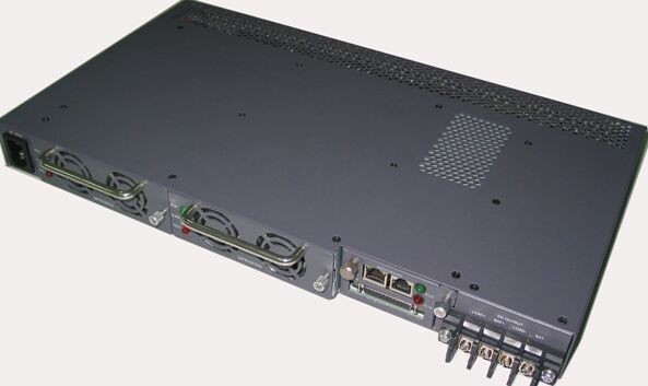
Chassis connects with external electric through system interface board. As shown in figure below:
1. Bracket 2. AC input socket with three-core
3. Rectifier module 4.Monitoring module
5. Signal interface 6. Output connectors
3.2 Process of electric connections
Electric connection between main cabinet and external component includes: connection of AC input line, connection of DC output and battery, connection of communication cables, connection of GND cables. The main requirements of electrical connection are safety and reliability. The followings are detailed description.
(1) AC input cable connections
The connectors for AC input cable are three-core AC input sockets on the front panel of system. The AC cable can be directly inserted to the connector.
(2) Connection of DC load cables
The terminals for output connection of power system are one screwed binding posts (4 P) and the terminals for load connection are LOAD+ and LOAD- (2PIN), locating on the front panel of the system. The cable can be directly crimped into the terminal.
a. The specifications and model of the cables shall be according to the engineering design requirements.
b. Connect the “+” end of the load to the corresponding connection terminal of LOAD“+”.(The cable section shall be 6mm2 above.)
c. Connect the “-”end of the load to the corresponding connection terminal of LOAD“-”.(The cable section shall be 6mm2 above.)
(3) Connection of DC battery cables
The terminals for output connection of power system are one screwed binding post (4 P) and the terminals for battery connection (2PIN) are signed as BAT+ and BAT-. The cable can be directly inserted to the terminal. The detailed process of battery connection is as following:
a. Prepare positive connection cables and negative connection cables(including terminals and polarity identifications ready).
b. Fasten up the battery connection cable
c. Connect one end of positive connection cable to the BAT. “+” ;
d. Connect one end of negative connection cable to the BAT. “-” ;
(4) Connection of GND cables
The fixed M6 screw of the bracket at the right functions as PE input.
(5) Connection of communication cables
RS-485-communication cable terminal of GPE4860C, locating on the front panel of monitoring module, functions as communication with the host.
RS-485 communication mode:
A. Connect one end of communication cable to RS-485 on front panel of GPE4860C
B. Connect the other end of communication cable to RS-485 of the host. “+”, “-” cable of RS485 in GPE4860C respectively correspond to “+”, “-” cable of RS-485 in the host.
Ethernet communication mode:
A. Connect one end of communication cable to LAN port on front panel of GPE4860C.
B. Connect the other end to Ethernet or directly apply the crossover cable (Cable 1 with cable 3, cable 2 with cable 6) with the PC.
4. GPM48M Monitoring Module
4.1 Functions of monitoring module
|
Item |
Remark |
|
Remote monitoring of the host |
The host can conduct enquiries, settings and control upon the monitoring and realize the remote message, remote sense and remote control. |
|
Rectifier management by monitoring module |
To send controlling orders or to get data from the rectifier module via RS485 communication. |
|
Battery management |
To manage low voltage, power down, equalizing/float charge, temperature compensation of the battery. |
|
Output management by monitoring module |
To inspect and control the system |
|
LED indicator |
Signal indication |
|
COM port signal |
|
|
For details, please refer to specifications of “GPM48M”. |
|
4.2 Installation of monitoring module
Handles on panel of rectifier module and monitoring module are equipped. When inserting component into the main cabinet, the operator shall clutch the handle with one hand while holding it with the other hand. Slowly push the component into its slot until the connection terminal on back of the component inserted into corresponding socket of system bar in the main cabinet. Finally, finish the installation by firmly fixing the screw on the panel to the main cabinet.
When removing component from the main cabinet, first screw off the bolt on panel then slowly remove the component from its slot while clutching the handle.
5. GPR4830A Rectifier Module
5.1 Properties
|
Item |
Unit |
Min. |
Typical |
Max. |
Remarks |
|
AC input voltage |
Vac |
90 |
220 |
290 |
|
|
AC input voltage frequency |
Hz |
45 |
50 |
65 |
Rated load |
|
Input power factor |
|
0.98 |
|
|
Rated voltage/ rated load |
|
Output voltage range |
Vdc |
42 |
54 |
58 |
|
|
Output current |
A |
0 |
30 |
|
176~290V ac Input |
|
Output voltage regulation |
|
|
|
±1% |
|
|
Ripple (Vp-p) |
mV |
|
|
200 |
With 0.1uF filmy capacitor and 10uF high frequency electrolyte capacitor, oscilloscope band width of 20MHz. |
|
Output power |
W |
0 |
1600 |
|
176-290V Input |
|
W |
0 |
600 |
|
90-175V Input |
|
|
Output efficiency |
% |
91 |
|
|
220V AC Input |
|
% |
83 |
|
|
110V AC Input |
|
|
Input over-voltage protection |
Vdc |
285 |
305 |
|
Tested with 15A, auto recoverable |
|
Input over-voltage recovery set point |
Vdc |
280 |
|
|
Hysteresis not less than 5V. |
|
Input under-voltage protection |
Vdc |
|
|
85 |
Tested with 4A, auto recoverable |
|
Input under-voltage recovery set point |
Vdc |
|
|
90 |
Hysteresis not less than 5V. |
|
Output over-voltage protection set point |
V |
58.5 |
59 |
61.5 |
Lock up |
|
Output current limiting |
A |
32 |
33 |
34 |
Auto recoverable |
|
Short circuit protection |
A |
Long-term short circuit endurable; Hiccup when short circuit detected; Auto recoverable |
|||
|
Thermal protection |
|
Auto recoverable under ambient temperature of 65°C. |
|||
|
For details, please refer to specifications of GPR4830A. |
|||||
5.2 Installation of rectifier module
Handles on panel of rectifier module and monitoring module are equipped. When inserting component into the main cabinet, the operator shall clutch the handle with one hand while holding it with the other hand. Slowly push the component into its slot until the connection terminal on back of the component inserted into corresponding socket of system bar in the main cabinet. Finally, finish the installation by firmly fixing the screw on the panel to the main cabinet.
When removing component from the main cabinet, first screw off the bolt on panel then slowly remove the component from its slot while clutching the handle.
6. Indications
|
LED indications on rectifier module |
|||
|
LED |
Color |
State |
Remark |
|
Operation |
Green |
On |
Normal operation |
|
Off |
Under abnormal situation |
||
|
Protection |
Yellow |
Off |
Normal operation |
|
Flicker |
Monitoring failure, communicaon failure |
||
|
Keep On |
Single fan failure, over-current, over-voltage |
||
|
Failure |
Red |
Off |
Normal operation |
|
Keep On |
Shutdown under situation of output over-voltage, over temperature, dual fans failure, short circuit at load side or no output caused by internal errors.. |
||
|
LED indications on monitoring module |
|||
|
LED |
Color |
State |
Remark |
|
Operation |
Green |
On |
Normal operation |
|
Off |
Under abnormal situation |
||
|
Protection |
Red |
Off |
Normal operation |
|
Keep On |
Fan failure, current limiting, externally connected sensor alarm, AC power down |
||
Contact Details
Other Products
-
EVCSE48400 power 23.2KW Rectifier With Wide Voltage Range Industrial Power Supply
-
GPE48200N,Telecom Power System/UPS/Rectifier/Switching Power,DC48V,200A,With Software,SNMP Protocol
-
GPE48150A,Telecom Power System/Base Station Rectifier,Input:90~290VAC,Output: -42~-58VDC
-
GPE48350E,Rectifier,DC48V,350A,Modular Rectifier System,With Monitoring Module,Software
-
GPE48120N,Rectifier,DC48V120A,With Monitoring Module,RS485/232,Ethernet Communication Port
-
Telecom Power System, UPS, Rectifier, Input: 90~280Vac; Output:-43.2~-57.6Vdc; Power:6420